Wednesday, August 19, 2020

Lighter Stronger Faster

As the goals of FS teams keep evolving, the fundamental principle is to build a fast and performing car that travels between two points in the fastest time possible. Turning to the age-old relation a=F/m, one can broadly split the overall investment of a team into two categories:
  1. Investments which increase F
  2. Investments which reduce m
Over the years (considering combustion cars), the fraction of investment over the second category has been steadily increasing. Today, weight-reduction is done on a grass-root level where teams are ready to invest the extra amount and time to reduce as less as 100 grams of weight. This may be attributed to two factors. Firstly, the upper cap in the engine capacity limits improvements in the powertrain subsystem. So teams tend to explore other areas (i.e, weight-reduction) and are willing to invest the extra resources for the overall betterment of the car. The other factor being the availability of materials which have exponentially less weight compared to the conventionally used materials (Al, Steel, etc.).

As the investment for weight reduction increased, it set the era for carbon fiber development (or the other way round too). Carbon fibre perfectly aligns with the goal of increasing the strength to weight ratio. Since carbon fibre offers a lot of flexibility and compatibility to the needs of engineers albeit being on the expensive side, they have been used extensively by teams. The following are the key features of our Composites R&D.

Having a proper setup for Manufacturing

One of the features by which composites differ from conventional materials like steel and aluminium is that the components are completely manufactured in-house and involve a lot of labour. It becomes really messy while handling the resin also when performing layup. So it is necessary to have a clean, spacious and comfortable setup to house all the moulds, fibre cloth, resin and other miscellaneous stuff required for layup with proper disposal (as there are a lot of single-time-use products involved) and cleaning procedure so that it doesn't get messy for the people doing the layup. Small setup hacks like having the resin container away from the unused fibre cloth helps because if any accidental spill happens and affects the unused fibre cloth, it will be a waste of money (as carbon fibre is really expensive).

Material Selection

Bi-Directional Woven Carbon Fibre Cloth

 For manufacturing one single component, there are a lot of materials involved and hence choosing materials might be tricky. For instance, the notable materials that have to be selected are the grade of carbon fiber, resin type, core material (if any), mould material and other miscellaneous materials like release agent and the finishing agent. The usual factors like budget, availability and properties must be considered for all these components carefully to narrow down the list of materials.

Obtaining the properties of the Laminate

Since the actual manufacturing is done by us, the properties are highly dependent on the manufacturing process and values are bound to change each time. Obviously these errors are unavoidable but we can improve on the simulations by testing and finding the properties of a laminate that was manufactured in-house and using that in the simulations rather than externally given values since it might have a different manufacturing background and may not be bankable. The tests include (but not limited to) static tests to determine required mechanical properties and tests to determine the fiber fraction in the laminate. Note that more than one set of tests might have to be done to check the consistency of the setup.

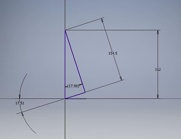
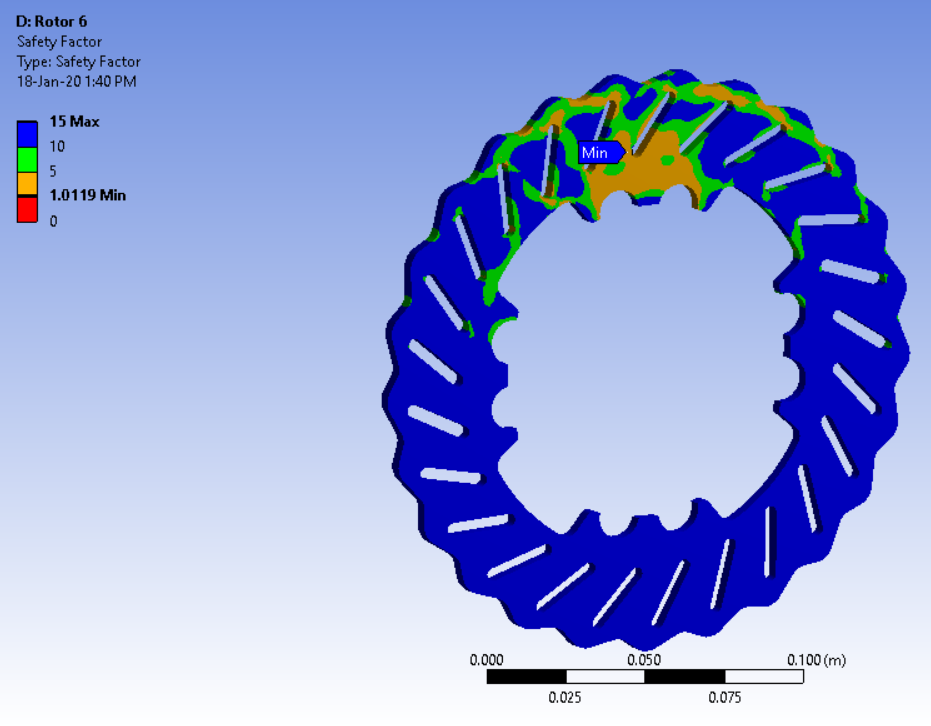
Structural Design and Simulation

An iteration from the composite Rear Bell Crank simulations

Most of the simulations are done using ANSYS ACP with the properties obtained from the above tests as the material properties. Most of the boundary conditions are given by the respective subsystems/rules. A manual estimation is carried out on the basis of the boundary conditions to determine the direction of the plies. Using that as an initial case, successive iterations are performed with changes in number/direction of the plies to get the most optimum combination. In the case of sandwich panels, the thickness is also iterated (if possible based on availability) and simulated to improve bending stiffness.

Determining the Manufacturing Process

Cutting Carbon fibre cloth before the Layup process

This is one of the key steps for the composites subsystem. Start from scratch. If at all, there is a proposal for an improvement in the manufacturing process, care has to be taken if the extra investment in the process actually yields better properties. This can be simply done by comparing the properties of samples with and without the new method and deciding if the improvement of the properties is significant enough for the team to put the extra effort (both money and time). To summarize, just check if the investment is worth it. For example, we found that vacuum bagging a sample after wet layup increases fiber content by a significant number thereby giving a green signal for the process. On the other hand, we still use 2D hotwire cutting to manufacture our moulds rather than machining. Note that the manufacturing process does not only involve the layup process, but also includes manufacturing the mould.
The other aspect to keep in mind is to consult the respective subsystems about the manufacturing method. For example, the aero components will have a priority on the surface finish on one side. These points have to be taken care of while designing the mould and manufacturing the component.

Our Progress as a Team

We started off our journey in composites by manufacturing the seat and now we manufacture the entire aerodynamic package, steering wheel and other miscellaneous components like switch panels and bodywork. With the development of composites, we look forward to expanding the use of composites in subsystems other than aerodynamics. The primary goal is to replace components on the car with composites as much as possible if it aids with weight reduction without compromise in other properties. A preliminary list of components are selected for design. These components will be tested and validated properly before giving the green light to be on the car.

This is how our team handles the Composites R&D for making our car. If you feel that we have missed something, please do let us know in the comments.

Sunday, June 14, 2020

BRAKING BAD

Braking is the first element in a Formula Student car's cornering phase. If the car isn't slowed down at the right point and with the right force on the pedal, it will compromise the remaining phases - hitting the apex, taking the right line, carrying the optimum speed through the corner, getting the power down on exit and completing a clean run to the next turn. This can have a major impact on a car’s lap time. A good brake system design provides the suitable braking power for the car to make quick corners and faster straights. The greater the average deceleration over the braking phase, lesser the time required to slow the car down for a corner and better the average speed.

Redesigning the Brake System


Here are some points to keep in mind and objectives which will help in designing the brake system:
  • Balance bar and spherical bearing mounted master cylinders offer better tunability over tandem master cylinders.
  • Floating rotors provide allowances for thermal expansion and caliper alignment.
  • Employing tire data to get the maximum braking performance and the optimum brake torque as well as the brake bias.
  • Parallelly working on selecting off-the-shelf components like master cylinders and calipers.
  • Maximizing convection of rotors to maintain optimum temperature.
  • Validating the above simulations using sensors.
Even if the brake system is excellent, it is the driver’s effort on the pedal that matters in the end that effectively stops the car. We can find how much pressure a driver can apply on the pedals with the help of weighing scales.
The maximum deceleration of the car depends on the properties of the tire. We employed the tire data to determine the braking torque for the front and rear. Do take a look at our MathWorks blog on the brake model which explains modelling the brake system in Simulink/Simscape.
The only physical constraint present is the dimension of the rotors which depends on the rim inner diameter. Maximizing the rotor diameter helped us to reduce the forces on the wheel assembly and to reduce the operating pressure.


Off the Shelf components


Calipers and master cylinders are the major components of the brake system. From the above information - braking torque and rotor size, the caliper to be used and the operating pressures are determined. We used Wilwood GP200 for all 4 corners. A master cylinder is required in order to achieve the required pressure. Using the driver effort, the pedal ratio and the master cylinder to be used for the front and rear is found.. The Tilton 77/78 series worked best for us. Other factors that we considered to select these components were cost, weight and availability.


Tilton master cylinder and Willwood brake caliper


The pedal assembly was then designed in order to get the required ratio. Essentially, the brake pedal - master cylinder combination is an inversion of the slider-crank mechanism. Various pedal positions and lengths as well as the master cylinder position were iterated to get the ratio right.

Brake pedal assembly line model in Inventor

Simulation and Validation


The rotors take up the kinetic energy lost during braking as heat energy. It is important to maintain optimum temperature to avoid brake fade and prevent altering the mechanical properties of the components. We have chosen cast iron as it has high hardness, high thermal capacity and better strength. And based on the brake pad performance, the operating temperature was chosen. The rotor geometry was designed to have maximum convection coefficient. This was done by simulating it in ANSYS Fluent. Once the required rotor profile was achieved, the transient thermal simulation was done to find the steady state temperature on the FSG autocross track. Now, it is an iterative process of getting the required convection coefficient for the optimum temperature. The final design was checked for the structural integrity by doing a fatigue simulation.

Static structural simulation in ANSYS

Sunday, May 31, 2020

GROUNDED BY WINGS


It's common knowledge that by placing an inverted airfoil on your car, you can increase the normal load your car experiences while in motion, but the question every team needs to answer before you decide to put it is:

IS IT WORTH IT ?

"If you think about it, it’s neither rocket science nor elementary math,it’s somewhere between, as a race-car engineer your job is to take 250-300 kgs of mass from Point A to Point B as fast as possible."  -Pat Clarke

So every decision you make should help you achieve the above goal, be it vehicle dynamics or powertrain decisions.
With regards to aerodynamics, for analogy if you think designing a race-car is like plucking fruits from a tree then aerodynamics is the fruit at the top of the tree.


Simulations help you Decide


You first need to decide if it’s worth getting that fruit. For this, we need an accurate model of the car and a good lap-simulation to understand if the car needs aerodynamics and whether or not the gain in laptime is worth the money and efforts you’re going to put in.
In our lap-sim we can enter the Coefficient of lift (CL) and drag (CD) and the frontal area. It assumes that the downforce is directly proportional the square of the velocity, and one cannot just enter whatever coefficients of lift and drag one presumes. In Macbeath, we found a trend which basically tells us what coefficient of lift is achievable for a race-car given a particular coefficient of drag. We use points from that graph in our lap-sim.
Note-Please try to approximate how much additional weight your aero package will be adding in the lap sim.


Time is of the essence, don't waste it


We used the FSG Auto-cross circuit as our base lap-sim, simply because it’s worth more points. Once you have an idea about the time you gain by using aerodynamics, analyse if you have the people, time and most importantly the money to translate that into reality. This is especially important when you’re trying aerodynamics for the first time. Taking all the above parameters into account you decide your target CL and CD values.


Pressure on the wings


Once you’ve decided the target CL and CD values for your race-car, the next step is to split these forces between the rear and front wings. This will decide the aerodynamic stability of your car. In other words, you need to decide where you want the centre of pressure (COP) of your car to be with respect to the centre of gravity (CG). This decides in what direction aerodynamics is going to aid your car. In simple terms if the COP is in front of CG, aero will aid oversteer and if it’s behind vice-versa. This doesn’t mean if you have COP in front of CG the car will oversteer, we’re talking about the proportional grip gain in the front and rear wheels due to aerodynamics. For a neutral car, we place the COP at CG and use simple moment and force balance equations to split the CL and CD of our car. During this phase, the aerodynamics sub-system needs to closely work with the vehicle dynamics sub-system to understand the car's behaviour with and without the aero-package.


Working on the Undertray


The size, position and the type of airfoils of a Formula Student aerodynamic package are often rule constrained and manufacturing limited. We begin first with 2D simulations where the first step is to select an airfoil for the main element and the flaps. We look for high lift airfoils which are easier to manufacture. Once the selection of an airfoil is done, we run a 2D simulation to decide it’s optimum operating angle of attack and then do a 3D simulation to co-relate it’s true downforce value. The addition of flap has a few more steps, we need to optimise the X and Y coordinates (the position of the flap with respect to the main element) and the angle of attack of the flaps to gain maximum downforce. This process is repeated until we gain maximum Lift/Drag ratio. The process is similar for the front and rear wing.
An undertray has the most potential in terms of aerodynamics as there is a lot to gain from the undertray in terms of downforce, mainly because of its proximity to the ground. The downforce produced by the undertray unlike the wings does not come with a drag penalty. So a good undertray design is very essential for a formula student car. An efficient undertray ensures sealing of air, optimum diffuser angle and sufficient mass-flow rate under the car as the undertray isn’t a single entity which you’re going to place on the car. It needs to work in harmony with the nose and the front wing of the car. So the design of an undertray is slightly different from the wings, ensuring an integrated undertray is very essential for gaining maximum performance from the floor.


Finalizing the Aero Package


This is basically part design, but should you make the decision of putting it on your car by just simulating it separately? Absolutely not!
We have a simplified 3D model of our car for CFD, once we’ve designed a part, we place it on our full car model and see if we’re gaining in terms of downforce. Once that is verified we then decide to put the part on our car. This is done basically to ensure an integrated Aero Package. After all this is done a final full car simulation is run to correlate our final downforce and drag values with what we’ve assumed before.


On Track Validation 


Validation is a very essential part of engineering. Needless to say if you’re going with aerodynamics in your car, the first thing the judge is going to ask you is whether you’ve validated your aero-package. A lot of validation techniques are available out there like wind tunnel testing. To verify our package , we have linear potentiometers on each spring which gives us the load on each tire while the car is in motion. We have the static load data on each potentiometer with different weights on the aerodynamic elements which is used as a database to create a neural network. The data obtained from the on-track run is filtered to eliminate the noise and is then fed into the neural network code which then directly gives us the downforce split up. This is how we can validate the CL of our car.
Another on-track validation technique is the Coast Down technique where you accelerate the car to a speed and engage the clutch, deceleration of the car is noted and then plotted with respect to speed, this way we validate our CD value.
The error percentages from simulation and the real life values are around 15 percent

These are the methods which our team uses in designing and testing our car's aero package. If you feel that we have missed something, please do let us know in the comments.


P.S- For knowing more about how our team performs simulations in MATLAB, click here.

Sunday, May 24, 2020

PLAN BEFORE YOU PRESENT


The Business Plan Presentation (BPP) Event is one of the three major static events held in any Formula Student Competition. We know that the main objective of this event is to assess and evaluate a team’s ability to develop a comprehensive business model that demonstrates their prototype-a race car. The team needs to deliver this business model to the judges, treating them as potential investors in their business, and explain how will it be executed in a realistic world and how can it generate profit.
While the rules were left unchanged in the FS 2020 Rule Book, the FB 2021 Rule Book specified some major changes like the omission of Deep Dive Topic and Pitch Video, the introduction of a Pitch Deck, conducting the Preliminary Round via video conference and an increase in weightage of Finances in terms of points.
For ensuring the success of a BPP, an FS team must always keep these points in mind.
 

PREPARATION


Getting to know how the competition works is the first significant step towards building up your plan for your model. The videos of many FSG BPP finals are available on the internet. We, as a team had sessions where we just watched all these videos to observe the top team’s presentations, their business models, their presentation sequences and of course, how they presented. It's not a bad idea to find some common aspects of these videos and to adopt them in your presentation. For example, we found out that most of the presentations had similar presentation sequences that gave them a good flow and were able to entertain the audience.
  

PLANNING


Planning is everything in Formula Student. Putting in extra hours in towards this will go a long way in helping you by minute amounts during the competition. So once you know how the competition itself works, planning a tentative schedule is a must. This timetable must include everything from when your business model gets finalized to when your presenters are ready with their terminology. As usual, everything does get delayed according to the Rule of π but planning out a rigorous schedule like this does give you clarity when making decisions and puts pressure on your colleagues to complete things before the deadline.


THE BUSINESS MODEL


From our experience, we find that the team with a unique idea always wins the event. Even if a team with a slightly sub-par idea had the best presentation, on an average people will prefer the former. Hence, this is the crux of the event which determines your position in the finals. The business model will dictate everything in the presentation-finances, customer base, the product etc. Adequate time must be spent formulating a unique idea. A background check also must be conducted whether the idea was used by teams in the competition before or not. Once you’re confident about the basic idea, a chain of thoughts can follow on how to make the idea and it’s presentation better. Also, a good idea needn't necessarily come from the BPP group only. Try having multiple brainstorming sessions with the whole team to see if you can come up with a killer idea together.


PRESENTATION


Our main takeaway from the BPP FSG finals videos was that most teams used PowerPoint for their presentations. Having tried out Prezi and other presentation software, we decided that PowerPoint would be the easiest one for multiple people to work on. As the presentation sequence has already been adopted from these videos, people who would present on specific topics worked separately on their slides following a common template. For example, a person who would be presenting finances took care of his slides but made sure the transition from the previous slide to his was smooth and in compliance with all the other slides. This saved loads of time and made sure a person was confident in his area of presentation. In the presentation, ensure that you have slides with less usage of words and the visual elements are compatible with the background. Also, keep in mind that it must be well-organized, as presentations which have a random order of sub-topics and are unorganized turn out to become a liability for the team. Another important feedback we got from FSG was for the need of backup slides. These backup slides include customer data, market share, detailed expenditure and revenue reports, financial calculations, a detailed SWOT analysis etc. During the Q&A session, these slides would back up our assumptions and calculations, convincing the judges that we did something legit.
 

FINANCIALS 


A business plan without a well-executed financial backing is surely going to take a toll on the score received.
The financials ideally must include the expenditure of the assumed company from the tiniest little expenses to the cost for setting up. Then comes the profit which the company has been receiving over the years and the projected profits, if any. The expenses must also include the salaries of all the staff and members who work in the company from the top to the bottom of the hierarchy. The numbers are equally important in order to understand the business' financials in a better way. Understanding the financial terms like Return on Investment, Risk Analysis, Exit strategies etc. will help you a lot in the Q&A session.


PRACTICE


Ultimately, after all the planning and preparation, it all boils down to one last thing -practice. This is to ensure that the team members who are going to present the BPP can do it smoothly and without any hiccups. As per the latest change in the BPP rules of FB 2021, teams need to ensure that their members who are going to present it have enough online practice sessions, so that they have full mastery over the material and don't crack under pressure while presenting it to the judges on the actual day.

These are the points that we take care of while preparing for the BPP of any FS competition. We hope that you take note of these points while preparing for your BPP. If you feel we missed something do let us know in the comments.

P.S-For those who don't know what the Rule of π is:-
"If you think that it will take a week for you to build a desk, it will actually take you 3.14 weeks. And if the budget for the said desk is $100, you will be out of $314 before it's all over."
(excerpt from Racecar: Searching for the Limit in Formula SAE by Matt Brown)

Lighter Stronger Faster

As the goals of FS teams keep evolving, the fundamental principle is to build a fast and performing car that travels between two points in...